Context diagrams
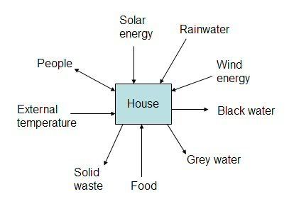
Systems Engineering is full of tools to aid you in mapping out your design requirements. One such useful visual aid is a context diagram. The concept is simple: for your system, represent all inputs and outputs as arrows leading into and out of the system. The challenge comes in accurately identifying the scope of your design and how it interacts with the surrounding environment.
Context diagrams are key for identifying the most vulnerable parts of any system – the interfaces. If the joining of two systems is poorly understood or designed, both can fail.
Depending on your particular situation, your inputs/outputs will likely be different from these examples shown below. For instance, if you use a ram pump for outside water, your community is urban, or you’re still connected to the electrical grid, your interfaces will be different.
Notice that many of the community interfaces are the same as for the house, even though the house in this example falls within the community. Also note that waste items such as grey water, black water, and solid waste do not exit the community – they are recycled within it.


0 Comments:
Post a Comment
<< Home